International Telecommunications Systems Group Corp
ITSGroup
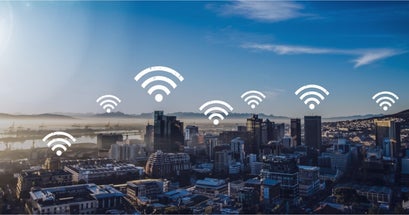
provides Cellular Telecommunications, Internet, Data, Television, WiFi
ITS Group is a wholly owned subsidiary of Avant-Garde-Technologies Corporation. ITS Group is multi-national telecommunication service provider. It has twelve decentralized subsidiaries where services are provided. Each subsidiary operates independently, but is managed by ITS Corporate which controls and sets policies and objectives. Each individual operating subsidiary provides cellular telecommunications services, television, broadband internet and WiFi services. There are over 40,000 outstanding engineers who work for ITS Group enabling it to provide services to over 28 million subscribers throughout the world. ITS Group owns its own fiber optic network and cellular towers infra-structure.
Pomp and Circumstance

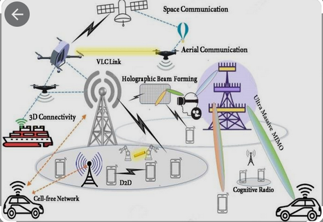
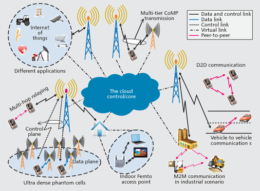
5G embodies the breadth and depth of innovative and comprehensive mobile wireless communications technology. The potential of 5G goes well beyond that of its predecessors. Some of the new applications it will enable are
- Multi-gigabit wireless mobile broadband
- Fixed broadband wireless access
- Augmented reality (AR) and virtual reality (VR)
- Autonomous vehicles
- Vehicle-to-everything (V2X) communications
- The mobile Internet of Things (IoT)
- The wireless industrial IoT (IIoT)
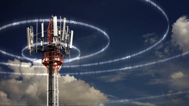
ITS Group owns and operates its own telecommunications infra-structure that includes towers, fiber-optic networks and television broadcasting. About 40% of ITS Group telecommunications network is 4G infra-structure for its wireless cellular services. ITS Group provides most of its services to individuals and businesses.

Age of Aquarius

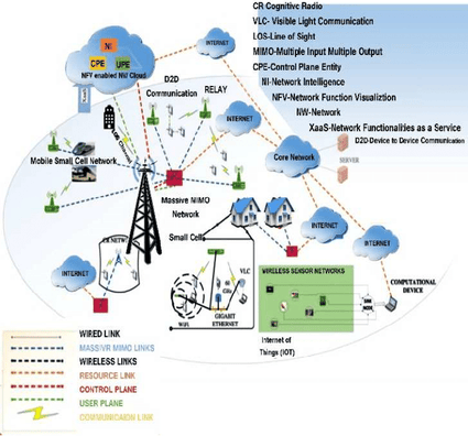
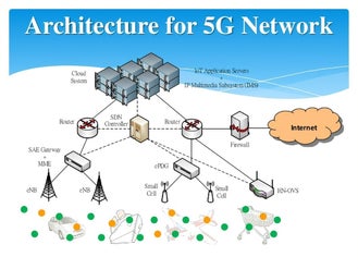
ITS Group is engaged in expanding its wireless telecommunications infra-structure to 5G. It will become the network foundation. Its cloud infra-structure is being designed to use micro-services on a Service Based Architecture (SBA). It uses Multi-Access Edge Computing (MEC) to extend to extend its architecture to edge locations. This becomes very important when 5G architecture is used for Internet of Things (IoT) applications.
5G technology is the latest standard for Long-Term Evolution (LTE). The first generation of LTE (1G) was primarily for wireless voice telecommunications. 2G then rapidly was deployed for short-messaging texting features. Shortly afterward 3G was deployed for the network core and enabled faster speed needed for smart-phones. 4G was deployed a few years later and provided high-data-transfer rates required for video applications with minimal buffering. 4G also enabled devices and services to be connected. 5G is the most recent wireless telecommunications technology of LTE.
Glen Campbell - Wichita Lineman

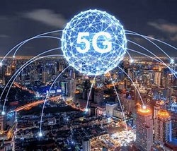
Although 5G is a new global wires standard, it is designed to connect everyone and everything. This includes people devices, machines, and objects. The 5G wireless solution provides much higher speed and lower latency. It is more reliable with massive network capacity and higher performance than prior standards. 5G will result in a major transformation of wireless telecommunications.
It is very expensive to deploy 5G. In order to get the most from a 5G deployment, high-performance Ultra Wideband is used. 5G is used together with the company’s massive fiber optic network and the millimeter wave spectrum to enable the greatest impact for users. It is expected that download speeds between 300 to 1,000 Mbps will result from 5G.
5G networks are vastly improving high-speed Internet connectivity around the globe and opening the door to a revolution in the Internet of Things (IoT). There are already billions of IoT devices, but the wider bandwidth and more efficient spectrum usage of 5G networks will allow far more devices to operate in close proximity without interfering with one another.
5G is much more than just the next iteration of mobile networks. Technological trends including cloud computing, artificial intelligence (AI) and machine learning (ML), AR and VR, and billions of connected devices are pushing the boundaries of the wireless communications system like never before.
5G technology provides faster, more reliable, and near-instant connections that will universally connect people and things. 5G allows everyone to experience live events and video games in real time, make phone and video calls that feel close and intimate, and pair smart devices with AI to create a customized and personalized environment for everyone.
Some of the ways that 5G boosts throughput are:
- Wider overall channel bandwidths enable sending more data through the air interface.
- Spatial multiplexing sends multiple independent streams of data through multiple antennas at a given time and frequency and uses enhanced channel feedback.
Enhanced channel feedback improves throughput because the signal is optimized for transmission with advanced channel coding. Massive multiple-input/multiple-output (massive MIMO) and beam-steering technologies improve throughput. Operating at mmWave frequencies introduces new challenges in path loss, blockage, and signal reflections. Beam steering is a key technology to overcome these issues. NR specifies new initial access procedures to ensure alignment of the directional transmissions used in beam steering. New initial access techniques use beam sweeping to have the base station transmit multiple beams and then identify the strongest beam and establish a communication link. Validating initial access, beam management, and throughput achieved through the wireless link are key factors for
successful beam steering implementation in 5G.

It will be years before 5G reaches its full potential, and 4G LTE networks will still be viable for a long time. But for IoT manufacturers and consumers alike, it’s helpful to understand what makes this technology different and how we can expect it to shape the landscape of cellular connectivity moving forward.
5G networks are designed to achieve a peak download speed of 20 Gbps and peak upload speed of 10 Gbps. The average rates are more like 100 Mbps for downloads and 50 Mbps for uploads. For comparison, the maximum theoretical data speeds for 4G LTE are 150 Mbps for downloads and 50 Mbps for uploads, with an average download speed of 20 Mbps and an average upload speed of 10 Mbps.
Starship - Nothing's Gonna Stop Us Now
5G’s average data speed is five times faster than 4G, and in theory, it could reach speeds more than 100 times faster. But 5G doesn’t just offer faster downlink and uplink speeds. It also has much lower latency as well. Latency is the time it takes to relay requests and responses from one device to another through a network. In a 5G network, the average latency is four milliseconds, and it can be as low as one millisecond for some applications. With a 4G connection, latency is closer to 50 milliseconds—making 5G’s latency more than 10 times lower than 4G.
Consumers can download full-length movies in high definition in seconds. And advanced IoT applications like self-driving cars, smart farming equipment, and remote healthcare will rely on 5Gs low latency and greater bandwidth.
-Eurythmics - Sweet Dreams (Are Made Of This)

In the past, faster speeds have come hand-in-hand with greater power consumption, but 5G builds on the power saving features of 4G to offer higher data throughput and lower power usage.
Speed isn’t the only advantage of 5G networks. 5G technology offers significantly wider bandwidth and greater flexibility in regard to how bands get used. This means 5G networks can maintain stable connectivity for a far greater number of devices in a concentrated area. And it’s the primary way 5G is changing the Internet of Things.
Oliver - Good morning starshine

Every network operates within specific frequency bands, and the devices on that network have to share that bandwidth. Over the years, advances in wireless technology and new approaches to connectivity have allowed providers to do more with the bandwidth they have. However, every network still faces the same limitation: too many devices using the same frequency bands within the same “cell” of a cellular network creates interference and disrupts connectivity.
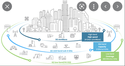
5G networks can facilitate connectivity on low frequencies below 1 Gigahertz (GHz), mid frequencies from 1 GHz to 6 GHz, and high frequencies from 6 GHz to over 100 GHz. Additionally, a 5G network can connect devices over both licensed and unlicensed bands, giving providers greater flexibility with how they use the radio frequency spectrum.
Born to Fly - Sara Evans

For comparison, commercial 4G networks can only use bands between 600 MHz and 3 GHz. While the substantially higher frequencies allow for greater data speeds, this also creates new challenges for engineers that want to take advantage of 5G.
A new innovation in 5G NR is bandwidth parts, where the carrier is subdivided for different purposes. Each bandwidth part has its own numerology and is signaled independently. One carrier can have mixed numerologies to support services in unlicensed bands and different levels of services — like power saving or multiplexing of numerologies.
Don McLean - American Pie
The use of millimeter-wave (mmWave) spectrum up to 52.6 gigahertz (GHz) is the key to enabling higher data throughput. At these higher frequencies, more contiguous spectrum is available to send more data through the channel. A maximum carrier bandwidth of up to 400 megahertz (MHz) and up to 16 component carriers (CCs), and allows multiple carriers to be combined to create up to 800 MHz of channel bandwidth.
Mini-slots are used as slot boundaries that are optimized for minimal latency. A standard slot has 14 orthogonal frequency-division multiplexing (OFDM) symbols. As the subcarrier spacing increases, the slot duration decreases. A mini-slot is shorter in duration than a
standard slot and can be located anywhere within the slot. A minislot is two, four, or seven OFDM symbols long. Mini-slots provide
low latency payloads with an immediate start time, without needing to wait for the start of a slot boundary.
A new innovation in 5G NR is bandwidth parts, where the carrier is subdivided for different purposes. Each bandwidth part has its own numerology and is signaled independently. One carrier can have mixed numerologies to support services in unlicensed bands and different levels of services, such as like power saving or multiplexing of numerologies.
Blue Moon Of Kentucky - Bill Monroe & His Bluegrass Boys


4G has been available for more than a decade. In that time, MNOs have built up massive 4G infrastructures, and innovators have found solutions to solve 4Gs shortcomings. 5G introduced new possibilities, but some new challenges came with it as well.
Low Power Wide Area Networks (LPWAN) are beginning to incorporate 5G technologies. Massive Machine-Type Communication (mMTC) is the 5G evolution of NB-IoT and LTE-M, and it will facilitate greater 5G coverage.
Coal Miner's Daughter - Loretta Lynn.
Higher radio frequencies have shorter wavelengths. And that means they can’t travel as far. This means that the “cells” of a 5G cellular network have to be smaller if an MNO wants to provide access to those high-frequency bands. 5G networks require more infrastructure, and that infrastructure offers less coverage.
Higher frequencies have a harder time penetrating buildings, which means they have poor indoor coverage. 5G can use bands in low and mid-range frequencies as well, but indoor applications will often not be able to use the higher bands.
5G connectivity is most useful in big cities where there’s a higher concentration of cellular devices (and greater demand for high-speed, low latency Internet). But it will take time for MNOs to build up the infrastructure needed to provide widespread 5G coverage.
5G connectivity is making room for tens of billions of new connected devices and more advanced applications for cellular IoT. This massive increase in the volume and capabilities of Internet-enabled devices will continue to present IoT security..
Every connected device creates opportunities for an application to serve as a gateway to an end user’s other connected devices, and botnets will likely grow in direct proportion to this increase, making them capable of inflicting even greater harm on a network through Distributed Denial-of-Service attacks. As IoT devices continue to collect and use more advanced data, the risk of unauthorized access increases as well.
Galveston - Glen Campbell
This has always been a challenge with IoT, and it will be exacerbated by the continued growth in this sector, but it’s also not a challenge that’s unique to 5G connectivity. In fact, 5G networks introduce new security mechanisms that make this connectivity more secure than other network types, such as the ability to encrypt end-to-end encryption of all network traffic, and mutual authentication.
Generally speaking, the longer a network has been around and the less complex its underlying technology is, the more modems IoT manufacturers have to choose from, and the less those modems cost. 5G is brand-new, and you need highly advanced modems and modules to connect to 5G networks. This can greatly increase your development costs. However, 5G mMTC is specifically designed for cellular IoT and will cost substantially less than other 5G tech.
5G’s ability to access higher radio frequencies has introduced a problem cellular carriers and manufacturers haven’t encountered before: they’re sharing bandwidth with satellites we use for weather forecasting. These high-frequency bands could significantly interfere with accurately tracking. .
Wireless carriers and the Federal Communications Commission (FCC) have countered that keeping 5G networks concentrated in urban areas and using beamforming technology will make this potential disruption insignificant.
Green Green Grass of Home - Porter Wagoner
Most major carriers have already deployed 5G networks, and they’ve sold millions of 5G compatible devices. But for now, 5G service is typically only available in larger cities. Some carriers already have 5G coverage in hundreds or thousands of cities, but on low frequency bands. Low-band 5G coverage will likely be widely available within a couple years, but high-speed 5G connections will take more time to roll out.
Honeycomb - Jimmie Rodgers
5G is the future of cellular connectivity. But for IoT, widespread 5G adoption is still in the distance. While 5G includes IoT-specific features, all of the relevant solutions are already present in LPWANs like LTE-M and NB-IoT. Unless the use case that requires very high data throughput and ultra-low latency, 5G not needed.
5G technology will be faster, more reliable, and near-instant connections that will universally connect people and things. 5G allows everyone to experience live events and video games in real time, make phone and video calls that feel close and intimate, and pair smart devices with AI to create a customized and personalized environment for everyone. Some of the practical beneficial uses for 5G are:
- Enhanced mobile broadband (eMBB): eMBB refers to the target 5G peak and average data rates, capacity, and coverage as compared to conventional mobile broadband. eMBB specifies a 5G design capable of supporting up to 20 gigabits per second (Gbps) in the downlink (DL) and 10 Gbps in the uplink (UL).
Massive machine-type communications (mMTC) supports 5G IoT use cases with billions of connected devices and sensors. This covers both low-data-rate/low-bandwidth devices with infrequent bursts of data requiring long battery life as well as very-high-bandwidth/data-rate devices.


Ultra-reliable and low-latency communications (URLLC) which focuses on applications that require fail-safe, real-time communications. Examples include autonomous vehicles, the industrial Internet, smart grids, infrastructure protection, and intelligent transportation systems.
The URLLC use case is partially achieved through a concept called mini-slots. In LTE, transmissions adhere to the standard slot boundaries, but they aren’t optimized for minimal latency. A standard slot has 14 orthogonal frequency-division multiplexing (OFDM) symbols. As the subcarrier spacing increases, the slot duration decreases. A mini-slot is shorter in duration than a standard slot and can be located anywhere within the slot. A minislot is two, four, or seven OFDM symbols long. Mini-slots provide low latency payloads with an immediate start time, without needing to wait for the start of a slot boundary.
The maximum carrier bandwidth for 5G is up to 100 MHz in FR1 (up to 7.125 GHz), or up to 400 MHz in FR2 (24.25 to 52.6 GHz). The standard allows for the aggregation of multiple carriers for up to 800 MHz of channel bandwidth. A new innovation in 5G NR is bandwidth parts, where the carrier is subdivided for different purposes. Each bandwidth part has its own numerology and is signaled independently. One carrier can have mixed numerologies to support services in unlicensed bands and different levels of services, such as like power saving or multiplexing of numerologies.

5G uses the cyclic prefix OFDM (CP-OFDM) waveform format. This format can be used in both the DL and the UL.. Having the same waveform in both the UL and the DL enables easier implementation of things like device-to-device communication in future releases. Discrete Fourier transform spread OFDM (DFT-s-OFDM) is an optional waveform in the UL. DFT-s-OFDM reduces the demand on user equipment (UE) transmission amplifiers, helping to extend battery life. 5G also allows for scalable OFDM numerology where the subcarrier spacings are no longer fixed to 15 kilohertz (kHz). Subcarrier spacing is determined by the formula 2n×15 kHz where n can be as low as –1. Lower frequency bands use 7.5, 15, 30, and 60 kHz subcarrier spacings, and higher frequency bands use 60, 120, and 240 kHz subcarrier spacings. Scalable numerology enables scalable slot duration to optimize throughput, latency, or reliability for different service levels.
Larger subcarrier spacing at higher frequencies also helps with the robustness of the waveform because integrated phase noise is a greater issue in mmWave designs
In an OFDM system, using CP mitigates the effects of channel delay spread and intersymbol interference (ISI). CP provides a buffer to protect the OFDM signal from ISI by repeating the end of the symbol at the start of the same symbol. Although using CP reduces the achievable data rate, it eliminates ISI up to the length of the CP. In 5G NR, as subcarrier spacing changes, CP length scales to adapt to the channel conditions.
Rainy Days - Mandy Barnet
5G boosts throughput in multiple ways. For example:
- Wider overall channel bandwidths enable sending more data through the air interface.
- Spatial multiplexing sends multiple independent streams of data through multiple antennas at a given time and frequency and uses enhanced channel feedback.


Channel state information (CSI), which refers to the known properties of a communication link, helps with 5G NR beamforming reliability. 5G NR specifies a new beam management framework for CSI acquisition to reduce coupling between CSI measurements and reporting to control different beams dynamically. CSI uses channel estimation to intelligently change the precoding and adapt the beam to a specific user. The better and more precise this CSI information, the better the link adaptation. CSI is also used for other purposes like equalization to adjust for frequency depended variations within the transmit (Tx) channel.
Glen Campbell - By The Time I Get To Phoenix
Enhanced channel feedback improves throughput because the signal is optimized for transmission with advanced channel coding. Massive multiple-input/multiple-output (massive MIMO) and beam-steering technologies improve throughput. Operating at mmWave frequencies introduces new challenges in path loss, blockage, and signal reflections. Beam steering is a key technology to overcome these issues. NR specifies new initial access procedures to ensure alignment of the directional transmissions used in beam steering. New initial access techniques use beam sweeping to have the base station transmit multiple beams and then identify the strongest beam and establish a communication link. Validating initial access, beam management, and throughput achieved through the wireless link are key factors for successful beam steering implementation in 5G.
5G is the fifth generation of cellular networks. Up to 100 times faster than 4G, 5G is creating never-before-seen opportunities for people and businesses.
Faster connectivity speeds, ultra-low latency and greater bandwidth is advancing societies, transforming industries and dramatically enhancing day-to-day experiences.
5G has evolved to include many new enhancements, such as:
- URLLC: Downlink and uplink enhancements, new prioritization and multiplexing, and multiple active configurations help achieve lower latency, higher reliability, and support for new use cases like motion control for factory automation and remote driving, and enhance use cases like AR/VR.
- Multi-access edge computing (MEC): Enabling lower latencies by moving things closer to the edge of the network, MEC is especially helpful for robotics, mission-critical autonomous factories, and remote driving applications. In addition to protocol enhancements, Rel-16 implements redundancy mechanisms and introduces a new intermediate session management function (I-SMF) node to control the user plane function (UPF) when the SMF isn’t able to.
- Wireless/wireline coexistence: New nodes improve interworking with non-3GPP systems for wireline access connectivity.
- Interference management: Cross link interference (CLI) assesses and mitigates DL and UL cross-interference between cells and UEs on the network. Remote interference management (RIM) helps the network understand and mitigate environmental (that is, atmospheric) issues.


5G runs on the same radio frequencies that are currently being used for your smartphone, on Wi-Fi networks and in satellite communications, but it enables technology to go a lot further.
Beyond being able to download a full-length HD movie to your phone in seconds (even from a crowded stadium), 5G is really about connecting things everywhere – reliably, without lag – so people can measure, understand and manage things in real time.
This has enormous potential to take telecommunications to the next level.
5G will do much more than significantly improve your network connection. It provides new opportunities, enabling us to deliver groundbreaking solutions that reach across society.
Imagine billions of connected devices gathering and sharing information in real time to reduce road accidents; or life-saving applications that can take flight thanks to lag-free guaranteed connections; or production lines so predictive they can prevent interruptions well before they occur.

5G is transforming industries
- 5G is the foundation for flexible, efficient and responsible business.
- Production lines autonomously reacting to supply and demand
- Digital replicas that can warn about real machinery faults ahead of time
- Logistic networks autonomously routing goods based on real-world conditions
- Full traceability down to the individual item at warehouses and ports
- Remote access to powerful robots and vehicles for improved safety in risky environments
- Increased use of IoT in agriculture to efficiently grow crops

Multiple-input/multiple-output (massive MIMO) is a new features and enhancements include support for multi-user MIMO (MU-MIMO) that increases capacity by allowing more UEs on the network, DL and UL control signaling for multi-beam operations to reduce latency and signaling overhead, and UE power enhancements.
Power efficiency: PDCCH lets a UE know when it needs to become active and when it can go inactive (or into sleep mode). MIMO layer adaption allows a UE to turn off unused receivers for longer periods of time to save power.
Unlicensed spectrum for 5G enables NR to operate in unlicensed spectrum through carrier aggregation (CA) with CCs in licensed and unlicensed spectrum, dual connectivity (DC) with LTE in licensed spectrum and NR in unlicensed spectrum, full NR operation in unlicensed spectrum, and NR cell with DL frequencies in unlicensed spectrum and UL frequencies in licensed spectrum.

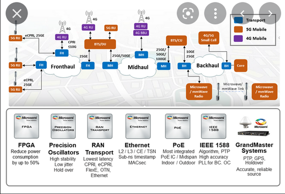
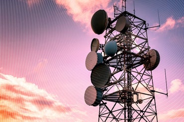
5G does not begin with the first mobile or portable device connection to the network. The network infrastructure must be in place to support the mobile and fixed devices. To recognize the benefits of 5G, a massive overall of the network infrastructure is needed. The process to change the infrastructure for 5G began with changes to the 4G networks and will continue for several years. Network densification is one of the many changes.
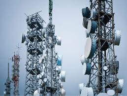
For higher capacities, faster speeds, lower latency and more system capacity to be realized, additional cell sites need to be installed. The additional cell sites will be in the form of enhanced Macro Cells, Small Cells and in-building Distributed Antenna Systems (DAS) networks.
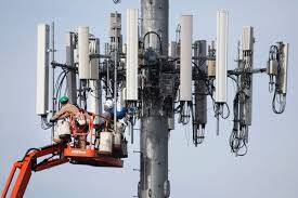
Unlike the larger tall tower large antenna array macro cell site, small cell is typically the size of a backpack and deployed on street lights, utility poles or sides of buildings. A small transmit/receive antenna is located on the top of the structure connected by a short coax cable run.

Enabling wireless networks to function requires a lot of wires and other passive components. Macro cell, small cell, and in-building DAS networks require connections via coax, copper and fiber optic “wires”. Other passive components include Ethernet cables, hybrid cables, splitters, couplers, tappers, attenuators, loads, adapters. RF Industries provides these products in standard and custom configurations. RF Industries, providing the “wires” for “wireless” networks.
5G will require the installation of hundreds of thousands of small cells. In 2017 about 13,000 were installed. In 2018 about 60,000 were installed. Future infrastructure deployments are estimated to be 80% small cell installations.
Over 65% of mobile wireless connections occur in a building, stadium or structure. With buildings naturally acting as a barrier to RF signals, an in-building DAS network is necessary for ubiquitous 5G coverage.

Fundamentals of cellular telecommunications
Cellular systems are widely used today and cellular technology needs to offer very efficient use of the available frequency spectrum. With billions of mobile phones in use around the globe today, it is necessary to re-use the available frequencies many times over without mutual interference of one cell phone to another.
It is this concept of frequency re-use that is at the very heart of cellular technology. However the infrastructure technology needed to support it is not simple, and it required a significant investment to bring the first cellular networks on line.
Early schemes for radio telephones schemes used a single central transmitter to cover a wide area. These radio telephone systems suffered from the limited number of channels that were available.
Often the waiting lists for connection were many times greater than the number of people that were actually connected. In view of these limitations this form of radio communications technology did not take off in a big way. Equipment was large and these radio communications systems were not convenient to use or carry around.
Cell system for frequency re-use
The method that is employed is to enable the frequencies to be re-used. Any radio transmitter will only have a certain coverage area. Beyond this the signal level will fall to a limited below which it cannot be used and will not cause significant interference to users associated with a different radio transmitter. This means that it is possible to re-use a channel once outside the range of the radio transmitter. The same is also true in the reverse direction for the receiver, where it will only be able to receive signals over a given range. In this way it is possible to arrange split up an area into several smaller regions, each covered by a different transmitter / receiver station.
These regions are conveniently known as cells, and give rise to the name of a "cellular" technology used today. Diagrammatically these cells are often shown as hexagonal shapes that conveniently fit together. In reality this is not the case. They have irregular boundaries because of the terrain over which they travel. Hills, buildings and other objects all cause the signal to be attenuated and diminish differently in each direction.
It is also very difficult to define the exact edge of a cell. The signal strength gradually reduces and towards the edge of the cell performance will fall. As the mobiles themselves will have different levels of sensitivity, this adds a further greying of the edge of the cell. Therefore it is never possible to have a sharp cut-off between cells. In some areas they may overlap, whereas in others there will be a "hole" in coverage.

Cell clusters
When devising the infrastructure technology of a cellular system, the interference between adjacent channels is reduced by allocating different frequency bands or channels to adjacent cells so that their coverage can overlap slightly without causing interference. In this way cells can be grouped together in what is termed a cluster.
Often these clusters contain seven cells, but other configurations are also possible. Seven is a convenient number, but there are a number of conflicting requirements that need to be balanced when choosing the number of cells in a cluster for a cellular system:
- Limiting interference levels
- Number of channels that can be allocated to each cell site
It is necessary to limit the interference between cells having the same frequency. The topology of the cell configuration has a large impact on this. The larger the number of cells in the cluster, the greater the distance between cells sharing the same frequencies.
In the ideal world it might be good to choose a large number of cells to be in each cluster. Unfortunately there are only a limited number of channels available. This means that the larger the number of cells in a cluster, the smaller the number available to each cell, and this reduces the capacity.
This means that there is a balance that needs to be made between the number of cells in a cluster, and the interference levels, and the capacity that is required.
Cell size
Even though the number of cells in a cluster in a cellular system can help govern the number of users that can be accommodated, by making all the cells smaller it is possible to increase the overall capacity of the cellular system. However a greater number of transmitter receiver or base stations are required if cells are made smaller and this increases the cost to the operator. Accordingly in areas where there are more users, small low power base stations are installed.
The different types of cells are given different names according to their size and function:
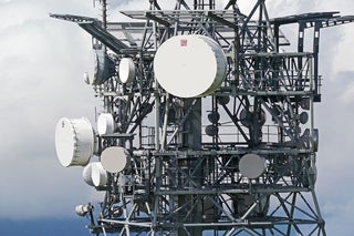
- Macro cells: Macro cells are large cells that are usually used for remote or sparsely populated areas. These may be 10 km or possibly more in diameter.
- Micro cells: Micro cells are those that are normally found in densely populated areas which may have a diameter of around 1 km.
- Pico cells: Picocells are generally used for covering very small areas such as particular areas of buildings, or possibly tunnels where coverage from a larger cell in the cellular system is not possible. Obviously for the small cells, the power levels used by the base stations are much lower and the antennas are not position to cover wide areas. In this way the coverage is minimised and the interference to adjacent cells is reduced.
- Selective cells: Sometimes cells termed selective cells may be used where full 360 degree coverage is not required. They may be used to fill in a hole in the coverage in the cellular system, or to address a problem such as the entrance to a tunnel etc.
- Umbrella cells: Another type of cells known as an umbrella cell is sometimes used in instances such as those where a heavily used road crosses an area where there are microcells. Under normal circumstances this would result in a large number of handovers as people driving along the road would quickly cross the microcells. An umbrella cell would take in the coverage of the microcells (but use different channels to those allocated to the microcells). However it would enable those people moving along the road to be handled by the umbrella cell and experience fewer handovers than if they had to pass from one microcell to the next.
Intrastructure technology
Although the illustrations used here to describe the basic infrastructure technology used for cellular systems refers to the original first generation systems, it serves to provide an overview of the basic cellular concepts that form the cornerstones of today's cellular technology. New techniques are being used, but the basic concepts employed are still in in use.
In any cellular system or cellular technology, it is necessary to have a scheme that enables several multiple users to gain access to it and use it simultaneously. As cellular technology has progressed different multiple access schemes have been used. They form the very core of the way in which the radio technology of the cellular system works.
There are four main multiple access schemes that are used in cellular systems ranging from the very first analogue cellular technologies to those cellular technologies that are being developed for use in the future. The multiple access schemes are known as FDMA, TDMA, CDMA and OFDMA.
Requirements for a multiple access scheme
In any cellular system it is necessary for it to be able have a scheme whereby it can handle multiple users at any given time. There are many ways of doing this, and as cellular technology has advanced, different techniques have been used.
There are a number of requirements that any multiple access scheme must be able to meet:
- Ability to handle several users without mutual interference.
- Ability to be able to maximise the spectrum efficiency
- Must be robust, enabling ease of handover between cells.

FDMA - Frequency Division Multiple Access
FDMA is the most straightforward of the multiple access schemes that have been used. As a subscriber comes onto the system, or swaps from one cell to the next, the network allocates a channel or frequency to each one. In this way the different subscribers are allocated a different slot and access to the network. As different frequencies are used, the system is naturally termed Frequency Division Multiple Access. This scheme was used by all analogue systems.
TDMA - Time Division Multiple Access
The second system came about with the transition to digital schemes for cellular technology. Here digital data could be split up in time and sent as bursts when required. As speech was digitised it could be sent in short data bursts, any small delay caused by sending the data in bursts would be short and not noticed. In this way it became possible to organise the system so that a given number of slots were available on a give transmission. Each subscriber would then be allocated a different time slot in which they could transmit or receive data. As different time slots are used for each subscriber to gain access to the system, it is known as time division multiple access. Obviously this only allows a certain number of users access to the system. Beyond this another channel may be used, so systems that use TDMA may also have elements of FDMA operation as well.

CDMA - Code Division Multiple Access
CDMA uses one of the aspects associated with the use of direct sequence spread spectrum. It can be seen from the article in the cellular telecoms area of this site that when extracting the required data from a DSSS signal it was necessary to have the correct spreading or chip code, and all other data from sources using different orthogonal chip codes would be rejected. It is therefore possible to allocate different users different codes, and use this as the means by which different users are given access to the system.
The scheme has been likened to being in a room filled with people all speaking different languages. Even though the noise level is very high, it is still possible to understand someone speaking in your own language. With CDMA different spreading or chip codes are used. When generating a direct sequence spread spectrum, the data to be transmitted is multiplied with spreading or chip code. This widens the spectrum of the signal, but it can only be decided in the receiver if it is again multiplied with the same spreading code. All signals that use different spreading codes are not seen, and are discarded in the process. Thus in the presence of a variety of signals it is possible to receive only the required one.
In this way the base station allocates different codes to different users and when it receives the signal it will use one code to receive the signal from one mobile, and another spreading code to receive the signal from a second mobile. In this way the same frequency channel can be used to serve a number of different mobiles.
OFDMA - Orthogonal Frequency Division Multiple Access
OFDMA is the form of multiple access scheme that is being considered for the fourth generation cellular technologies along with the evolutions for the third generation cellular systems (LTE for UMTS / W-CDMA and UMB for CDMA2000).
As the name implies, OFDMA is based around OFDM. This is a technology that utilises a large number of close spaced carriers.
To utilise OFDM as a multiple access scheme for cellular technology, two different methods are used, one for the uplink and one for the downlink. In the downlink, the mobile receives the whole signal transmitted by the base station and extracts the data destined for the particular mobile. In the uplink, one or more carriers are allocated to each handset dependent upon the data to be transmitted, etc. In this way the cellular network is able to control how the data is to be sent and received.
To utilise OFDM as a multiple access scheme for cellular technology, two different methods are used, one for the uplink and one for the downlink. In the downlink, the mobile receives the whole signal transmitted by the base station and extracts the data destined for the particular mobile. In the uplink, one or more carriers are allocated to each handset dependent upon the data to be transmitted, etc. In this way the cellular network is able to control how the data is to be sent and received.
One of the key elements of any radio communications system is the way in which radio communications are maintained in both directions. Terms including simplex, duplex, frequency division duplex, FDD, and time division duplex, TDD, are all methods that can be used.
For cellular systems it is necessary that it is possible to talk or send data in both directions simultaneously, and this places a number of constraints on the schemes that may be used to control the transmission flow. As it is such a key element of the system, it is necessary to settle on the scheme that will be used from outset. As a result the duplex scheme to be used forms a very basic part of the overall specification for the cellular (or any radio communications system) that is to be used.
The different schemes for controlling the transmission range from simplex through half duplex to full duplex. Furthermore, schemes such as TDD and FDD need to be defined for the system depending upon its application and the traffic it is likely to carry. Many aspects of the performance will be governed by aspects such as whether FDD or TDD is used.
Transmission control schemes
There are a variety of different ways of controlling the two way passage of information using two transmitters. They range in complexity from the simplest systems requiring the least complex circuitry and providing more basic performance, to more complex systems providing higher levels of performance. However each scheme has its own advantages and disadvantages.
- Simplex: Although the definition of simplex is not always clear the ANSI (American National Standards Institute) definition for a simplex transmission, is one that can only occur in one direction. One example of this may be a broadcast system. Occasionally simplex may refer to a half duplex scheme as described below.
- Half duplex: This is a duplex scheme whereby communication is possible in two directions, but communication is only possible in one direction at a time. If one transmitter is transmitting, the other one must wait until the first stops before transmitting. This form of communication is used for walkie-talkies, CB, etc. It may also be referred to as Simplex, in some circumstances although exact definitions can be contradictory at times.
- Full duplex: Full duplex, which is sometimes referred to simply as duplex is a scheme whereby transmissions may be sent in both directions simultaneously. However it sis till necessary for the transmissions to be separated in some way to enable the receivers to receive signals at the same time as transmissions are being made. There are two ways of achieving this. One is to use frequency separation (frequency division duplex, FDD, and the other is to use time, time division duplex, TDD.
The two schemes are both widely used. Some cellular systems use TDD while others use FDD. Some standards also allow for the use of either as both FDD and TDD have their own advantages and disadvantages.
Frequency division duplex, FDD
Frequency division duplex, FDD, uses the idea that the transmission and reception of signals are achieved simultaneously using two different frequencies. Using FDD it is possible to transmit and receive signals simultaneously as the receiver is not tuned to the same frequency as the transmitter as shown.
For the FDD scheme to operate satisfactorily, it is necessary that the frequency, i.e. channel separation between the transmission and reception frequencies must be sufficient to enable the receiver not to be unduly affected by the transmitter signal. This is known as the guard band.
Receiver blocking is an important issue with FDD schemes, and often highly selective filters may be required. For cellular systems using FDD, filters are required within the base station and also the handset to ensure sufficient isolation of the transmitter signal without desensitising the receiver. While cost is not such a significant driver for the base stations, placing a filter into the handsets is more of an issue.
The use of an FDD system does enable true simultaneous transmission and reception of signals. However two channels are required and this may not always use the available spectrum efficiently.
The spectrum used for FDD systems is allocated by the regulatory authorities. As there is a frequency separation between the uplink and downlink directions, it is not normally possible to reallocate spectrum to change the balance between the capacity of the uplink and downlink directions if there are changing capacity requirements for each direction.Time division duplex, TDD
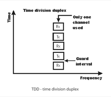
The other system uses only a single frequency and it shares the channel between transmission and reception, spacing them apart by multiplexing the two signals on a time basis. Time Division Duplex, TDD, is used with data transmissions (data or digitised voice), transmitting a short burst of data in each direction. As the transmission periods are relatively short no time delay is noticed on voice transmissions resulting from the time delays introduced by using TDD.
TDD - time division duplex
While FDD transmissions require a guard band between the transmitter and receiver frequencies, TDD schemes require a guard time or guard interval between transmission and reception. This must be sufficient to allow the signals travelling from the remote transmitter to arrive before a transmission is started and the receiver inhibited. Although this delay is relatively short, when changing between transmission and reception many times a second, even a small guard time can reduce the efficiency of the system as a percentage of the time must be used for the guard interval. For systems communicating over short distances, e.g. up to a mile or so the guard interval is normally small and acceptable. For greater distances it may become an issue.
The guard interval required for TDD will comprise two main elements:
- A time allowance for the propagation delay for any transmissions from the remote transmitter to arrive at the receiver. This will depend upon the distances involved, but it takes 3.3 microseconds to travel a kilometre, 5.4 microseconds to travel 1 mile.
- A time allowance for the transmitter receiver to change from receive to transmit. Switching speeds can vary considerably between equipments but can take a few microseconds.
As a result, TDD is not normally suitable for use over long distances as the guard time increases and the channel efficiency falls. Also transmit receive switching must be fast.
It is often found that traffic in both directions is not balanced. Typically there is more data travelling in the downlink direction of a cellular telecommunications system. This means that, ideally, the capacity should be greater in the downlink direction. Using a TDD system it is possible to change the capacity in either direction relatively easily by changing the number of time slots allocated to each direction. Often this is dynamically configurable so it can be altered to match the demand.
A further aspect to be noted with TDD transmissions is the aspect of latency. As data may not be able to be routed immediately onto a transmission as a result of the time multiplexing between transmit and receive, there will be a small delay between the data being generated and it being actually transmitted. Typically this may be a few milliseconds dependent upon the frame times, but in some applications it may be of interest, although for normal digitised speak, there would be no noticeable delay.
Transmission directions
It is often necessary to distinguish between the link from the mobile to the base station, and the link from the base station to the mobile. This is often necessary not only when talking of the duplex schemes in use.
There are obviously two links:
- Downlink, or forward link: This is the link from the base station to the mobile or user equipment. The words may be abbreviated to DL or D/L.
- Uplink, or reverse link: This is the link from the mobile or user equipment to the base station. The words uplink may be abbreviated to UL or U/L.
Although the definitions of transmission direction in this format are generally sued for cellular communications, they may also be used in other areas where a base station and mobile or remote equipments are in use.
TDD FDD Comparison
Both TDD and FDD have their advantages and each can be used to advantage in different circumstances. Before deciding on a particular type of duplex scheme, it is necessary to analyse the advantages and disadvantages of each. An FDD TDD comparison will then determine the best option.
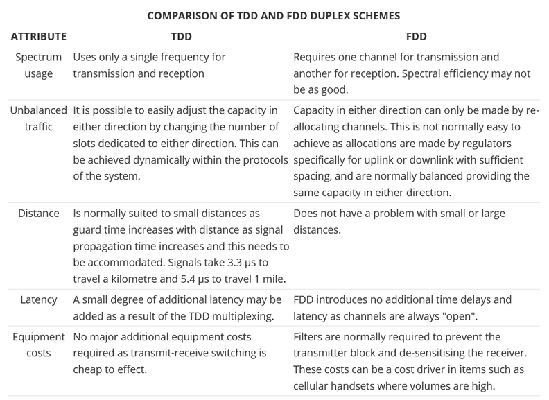
Comparison of TDD and FDD duplex schemes Attribute TDD FDD Spectrum usage Uses only a single frequency for transmission and reception Requires one channel for transmission and another for reception. Spectral efficiency may not be as good. Unbalanced traffic It is possible to easily adjust the capacity in either direction by changing the number of slots dedicated to either direction. This can be achieved dynamically within the protocols of the system. Capacity in either direction can only be made by re-allocating channels. This is not normally easy to achieve as allocations are made by regulators specifically for uplink or downlink with sufficient spacing, and are normally balanced providing the same capacity in either direction. Distance Is normally suited to small distances as guard time increases with distance as signal propagation time increases and this needs to be accommodated. Signals take 3.3 µs to travel a kilometre and 5.4 µs to travel 1 mile. Does not have a problem with small or large distances. Latency A small degree of additional latency may be added as a result of the TDD multiplexing. FDD introduces no additional time delays and latency as channels are always "open". Equipment costs No major additional equipment costs required as transmit-receive switching is cheap to effect. Filters are normally required to prevent the transmitter block and de-sensitising the receiver. These costs can be a cost driver in items such as cellular handsets where volumes are high.
In view of this TDD FDD comparison, TDD systems are often used in scenarios where short distances are required, with the possibility of unbalanced data traffic. FDD schemes are better over greater distances and where the traffic is balanced, i.e. similar in both directions.
Both TDD and FDD duplex schemes have their own advantages and disadvantages. Accordingly they are used in different applications, or in different areas where the advantages of TDD and FDD can be used to the greatest advantage. In view of the advantages of unbalanced uplinks and downlinks in short range cellular and wireless applications, TDD solutions are finding an increasing number of applications, while FDD systems are still in widespread use where the there are different requirements.
One of the key elements of any radio communications system is the way in which radio communications are maintained in both directions. Terms including simplex, duplex, frequency division duplex, FDD, and time division duplex, TDD, are all methods that can be used.
For cellular systems it is necessary that it is possible to talk or send data in both directions simultaneously, and this places a number of constraints on the schemes that may be used to control the transmission flow. As it is such a key element of the system, it is necessary to settle on the scheme that will be used from outset. As a result the duplex scheme to be used forms a very basic part of the overall specification for the cellular (or any radio communications system) that is to be used.
The different schemes for controlling the transmission range from simplex through half duplex to full duplex. Furthermore, schemes such as TDD and FDD need to be defined for the system depending upon its application and the traffic it is likely to carry. Many aspects of the performance will be governed by aspects such as whether FDD or TDD is used.

Transmission control schemes
There are a variety of different ways of controlling the two way passage of information using two transmitters. They range in complexity from the simplest systems requiring the least complex circuitry and providing more basic performance, to more complex systems providing higher levels of performance. However each scheme has its own advantages and disadvantages.
- Simplex: Although the definition of simplex is not always clear the ANSI (American National Standards Institute) definition for a simplex transmission, is one that can only occur in one direction. One example of this may be a broadcast system. Occasionally simplex may refer to a half duplex scheme as described below.
- Half duplex: This is a duplex scheme whereby communication is possible in two directions, but communication is only possible in one direction at a time. If one transmitter is transmitting, the other one must wait until the first stops before transmitting. This form of communication is used for walkie-talkies, CB, etc. It may also be referred to as Simplex, in some circumstances although exact definitions can be contradictory at times.
- Full duplex: Full duplex, which is sometimes referred to simply as duplex is a scheme whereby transmissions may be sent in both directions simultaneously. However it sis till necessary for the transmissions to be separated in some way to enable the receivers to receive signals at the same time as transmissions are being made. There are two ways of achieving this. One is to use frequency separation (frequency division duplex, FDD, and the other is to use time, time division duplex, TDD.
The two schemes are both widely used. Some cellular systems use TDD while others use FDD. Some standards also allow for the use of either as both FDD and TDD have their own advantages and disadvantages.
Frequency division duplex, FDD
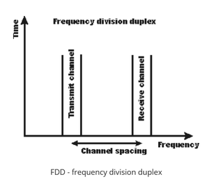
Frequency division duplex, FDD, uses the idea that the transmission and reception of signals are achieved simultaneously using two different frequencies. Using FDD it is possible to transmit and receive signals simultaneously as the receiver is not tuned to the same frequency as the transmitter.
FDD - frequency division duplex
For the FDD scheme to operate satisfactorily, it is necessary that the frequency, i.e. channel separation between the transmission and reception frequencies must be sufficient to enable the receiver not to be unduly affected by the transmitter signal. This is known as the guard band.
Receiver blocking is an important issue with FDD schemes, and often highly selective filters may be required. For cellular systems using FDD, filters are required within the base station and also the handset to ensure sufficient isolation of the transmitter signal without desensitising the receiver. While cost is not such a significant driver for the base stations, placing a filter into the handsets is more of an issue.
The use of an FDD system does enable true simultaneous transmission and reception of signals. However two channels are required and this may not always use the available spectrum efficiently.
The spectrum used for FDD systems is allocated by the regulatory authorities. As there is a frequency separation between the uplink and downlink directions, it is not normally possible to reallocate spectrum to change the balance between the capacity of the uplink and downlink directions if there are changing capacity requirements for each direction.Time division duplex, TDD
The other system uses only a single frequency and it shares the channel between transmission and reception, spacing them apart by multiplexing the two signals on a time basis. Time Division Duplex, TDD, is used with data transmissions (data or digitised voice), transmitting a short burst of data in each direction. As the transmission periods are relatively short no time delay is noticed on voice transmissions resulting from the time delays introduced by using TDD.
TDD - time division duplex
While FDD transmissions require a guard band between the transmitter and receiver frequencies, TDD schemes require a guard time or guard interval between transmission and reception. This must be sufficient to allow the signals travelling from the remote transmitter to arrive before a transmission is started and the receiver inhibited. Although this delay is relatively short, when changing between transmission and reception many times a second, even a small guard time can reduce the efficiency of the system as a percentage of the time must be used for the guard interval. For systems communicating over short distances, e.g. up to a mile or so the guard interval is normally small and acceptable. For greater distances it may become an issue.
The guard interval required for TDD will comprise two main elements:
- A time allowance for the propagation delay for any transmissions from the remote transmitter to arrive at the receiver. This will depend upon the distances involved, but it takes 3.3 microseconds to travel a kilometre, 5.4 microseconds to travel 1 mile.
- A time allowance for the transmitter receiver to change from receive to transmit. Switching speeds can vary considerably between equipments but can take a few microseconds.
As a result, TDD is not normally suitable for use over long distances as the guard time increases and the channel efficiency falls. Also transmit receive switching must be fast.
It is often found that traffic in both directions is not balanced. Typically there is more data travelling in the downlink direction of a cellular telecommunications system. This means that, ideally, the capacity should be greater in the downlink direction. Using a TDD system it is possible to change the capacity in either direction relatively easily by changing the number of time slots allocated to each direction. Often this is dynamically configurable so it can be altered to match the demand.
A further aspect to be noted with TDD transmissions is the aspect of latency. As data may not be able to be routed immediately onto a transmission as a result of the time multiplexing between transmit and receive, there will be a small delay between the data being generated and it being actually transmitted. Typically this may be a few milliseconds dependent upon the frame times, but in some applications it may be of interest, although for normal digitised speak, there would be no noticeable delay.
Transmission directions
It is often necessary to distinguish between the link from the mobile to the base station, and the link from the base station to the mobile. This is often necessary not only when talking of the duplex schemes in use.
There are obviously two links:
- Downlink, or forward link: This is the link from the base station to the mobile or user equipment. The words may be abbreviated to DL or D/L.
- Uplink, or reverse link: This is the link from the mobile or user equipment to the base station. The words uplink may be abbreviated to UL or U/L.
Although the definitions of transmission direction in this format are generally sued for cellular communications, they may also be used in other areas where a base station and mobile or remote equipments are in use.
TDD FDD Comparison
Both TDD and FDD have their advantages and each can be used to advantage in different circumstances. Before deciding on a particular type of duplex scheme, it is necessary to analyse the advantages and disadvantages of each. An FDD TDD comparison will then determine the best option.
Comparison of TDD and FDD duplex schemes Attribute TDD FDD Spectrum usage Uses only a single frequency for transmission and reception Requires one channel for transmission and another for reception. Spectral efficiency may not be as good. Unbalanced traffic It is possible to easily adjust the capacity in either direction by changing the number of slots dedicated to either direction. This can be achieved dynamically within the protocols of the system. Capacity in either direction can only be made by re-allocating channels. This is not normally easy to achieve as allocations are made by regulators specifically for uplink or downlink with sufficient spacing, and are normally balanced providing the same capacity in either direction. Distance Is normally suited to small distances as guard time increases with distance as signal propagation time increases and this needs to be accommodated. Signals take 3.3 µs to travel a kilometre and 5.4 µs to travel 1 mile. Does not have a problem with small or large distances. Latency A small degree of additional latency may be added as a result of the TDD multiplexing. FDD introduces no additional time delays and latency as channels are always "open". Equipment costs No major additional equipment costs required as transmit-receive switching is cheap to effect. Filters are normally required to prevent the transmitter block and de-sensitising the receiver. These costs can be a cost driver in items such as cellular handsets where volumes are high.
In view of this TDD FDD comparison, TDD systems are often used in scenarios where short distances are required, with the possibility of unbalanced data traffic. FDD schemes are better over greater distances and where the traffic is balanced, i.e. similar in both directions.
Both TDD and FDD duplex schemes have their own advantages and disadvantages. Accordingly they are used in different applications, or in different areas where the advantages of TDD and FDD can be used to the greatest advantage. In view of the advantages of unbalanced uplinks and downlinks in short range cellular and wireless applications, TDD solutions are finding an increasing number of applications, while FDD systems are still in widespread use where the there are different requirements.
The Mobile Phone
The mobile phone or cell phone as it is often called is equally important to the network in the operation of the complete cellular telecommunications network. Despite the huge numbers that are made, they still cost a significant amount to manufacture, discounts being offered to users as incentives to use a particular network. Their cost is a reflection of the complexity of the mobile phone electronics. They comprise several different areas of electronics, from radio frequency (RF) to signal processing, and general processing.
The design of a cell phone is particularly challenging. They need to offer high levels of performance, while being able to fit into a very small space, and in addition tot his the electronics circuitry needs to consume very little power so that the life between charges can be maintained.
Mobile phone contents
Mobile phones contain a large amount of circuitry, each of which is carefully designed to optimise its performance. The cell phone comprises analogue electronics as well as digital circuits ranging from processors to display and keypad electronics. A mobile phone typically consists of a single board, but within this there are a number of distinct functional areas, but designed to integrate to become a complete mobile phone:
- Radio frequency - receiver and transmitter
- Digital signal processing
- Analogue / digital conversion
- Control processor
- SIM or USIM card
- Power control and battery

Radio frequency elements
The radio frequency section of the mobile phone is one of the crucial areas of the cell phone design. This area of the mobile phone contains all the transmitter and receiver circuits. Normally direct conversion techniques are generally used in the design for the mobile phone receiver.
The signal output from the receiver is applied to what is termed an IQ demodulator. Here the data in the form of "In-phase" and "Quadrature" components is applied to the IQ demodulator and the raw data extracted for further processing by the phone.
On the transmit side one of the key elements of the circuit design is to keep the battery consumption to a minimum. For GSM this is not too much of a problem. The modulation used is Gaussian Minimum Shift Keying. This form of signal does not incorporate amplitude variations and accordingly it does not need linear amplifiers. This is a distinct advantage because non linear RF amplifiers are more efficient than linear RF amplifiers.
Unfortunately EDGE uses eight point phase shift keying (8PSK) and this requires a linear RF amplifier. As linear amplifiers consume considerably more current this is a distinct disadvantage. To overcome this problem the design for the mobile phone is organised so that phase information is added to the signal at an early stage of the transmitter chain, and the amplitude information is added at the final amplifier.
Analogue to Digital Conversion
Another crucial area of any mobile phone design is the circuitry that converts the signals between analogue and digital formats that are used in different areas. The radio frequency sections of the design use analogue techniques, whereas the processing is all digital.
The digital / analogue conversion circuitry enables the voice to be converted either from analogue or to digital a digital format for the send path, but also between digital and analogue for the receive path. It also provides functions such as providing analogue voltages to steer the VCO in the synthesizer as well as monitoring of the battery voltage, especially during charging. It also provides the conversion for the audio signals to and from the microphone and earpiece so that they can interface with the digital signal processing functions.
Another function that may sometimes be included in this area of the mobile phone design or within the DSP is that of the voice codecs. As the voice data needs to be compressed to enable it to be contained within the maximum allowable data rate, the signal needs to be digitally compressed. This is undertaken using what is termed a codec.
There are a number of codec schemes that can be used, all of which are generally supported by the base stations. The first one to be used in GSM was known as LPC-RPE (Linear Prediction Coding - Regular Pulse Excitation). However another scheme known as AMR (Adaptive Multi-Rate) is now widely used as it enables the data rate to be further reduced when conditions permit without impairing the speech quality too much. By reducing the speech data rate, further capacity is freed up on the network.
Digital Signal Processing
The DSP components of the mobile phone design undertake all the signal processing. Processes such as the radio frequency filtering and signal conditioning at the lower frequencies are undertaken by this circuitry. In addition to this, equalisation and correction for multipath effects is undertaken in this area of the design.
Although these processors are traditionally current hungry, the current processors enable the signal processing to be undertaken in a far more power effective manner than if analogue circuits are used.
Control processor
The control processor is at the heart of the design of the phone. It controls all the processes occurring in the phone from the MMI (Man machine interface) which monitors the keypad presses and arranging for the information to be displayed on the screen. It also looks after all the other elements of the MMI including all the menus that can be found on the phone.
Another function of the control processor is to manage the interface with the mobile network base station. The software required for this is known as the protocol stack and it enables the phone to register, make and receive calls, terminate them and also handle the handovers that are needed when the phone moves from one cell to the next. Additionally the software formats the data to be transmitted into the correct format with error correction codes included. Accordingly the load on this processor can be quite high, especially when there are interactions with the network.
The protocols used to interact with the network are becoming increasingly complicated with the progression from 2G to 3G. Along with the increasing number of handset applications the load on the processor is increasing. To combat this, the design for this area of the phone circuitry often uses ARM processors. This enables high levels of processing to be achieved for relatively low levels of current drain.
A further application handled by this area of the design of the mobile phone is the monitoring the state pf the battery and control of the charging. In view of the sophisticated monitoring and control required to ensure that the battery is properly charged and the user can be informed about the level of charge left, this is an important area of the design.
Battery
Battery design and technology has moved on considerably in the last few years. This has enabled mobile phones to operate for much longer. Initially nickel cadmium cells were used, but these migrated to nickel-metal-hydride cells and then to lithium ion cells. With phones becoming smaller and requiring to operate for longer from a single charge, the capacity of the battery is very important, and all the time the performance of these cells is being improved.
Although mobile phones are one of the most commonplace pieces of electronics equipment these days, they are nevertheless complicated inside. An understanding of the mobile phone basics can often be useful when looking at the way a cellular network and cellular technology in general works.
Connectivity in both wired and wireless forms is part of everyday life. From wired and fibre broadband to mobile communications - 2G, 3G, 4G and 5G, Wi-Fi, Bluetooth and many other wireless technologies through to standards like Ethernet, USB and many others. Wi-Fi is particularly important as demonstrated by the number of Wi-Fi routers, Wi-Fi repeaters and the like that are available for sale.
Mobile phones / cellular telecommunications
Wireless Connectivity
This addresses a variety of topics associated with wireless conenctivity. Everything from Wi-Fi, Wi-FI routers and repeaters, etc through to other forms of wireless conenctivity including Bluetooth, LoRa, NFC and many more. With the technology for Smart homes and cities becoming more commonplace, these technologies are being used increasingly.
- WiFi - IEEE 802.11
- Bluetooth
- RFID: radio frequency identification
- NFC: near field communication
- IEEE 802.15.4
- WiMAX
Wired Connectivity
Although wireless technologies like Wi-Fi are widely used, wired connectivity is important. Ethernet is once such example as it is used for many computer conenctions. Items like Ethernet cables and many more can be found, although with other wired connectivity areas like USB, serial communications and networking solutions like NFV and SDN.
- Erlang
- E carrier
- Optical fibre communications
- VoIP
- Networking fundamentals
- What is the Cloud
- Network, functions virtualization, NFV
- Software defined networking, SDN
- SD-WAN
Radio systems
Orthogonal Frequency Division Multiplex (OFDM)
Orthogonal Frequency Division Multiplex, OFDM is a form of signal format that uses a large number of close spaced carriers that are each modulated with low rate data stream. The close spaced signals would normally be expected to interfere with each other, but by making the signals orthogonal to each other there is no mutual interference. The data to be transmitted is shared across all the carriers and this provides resilience against selective fading from multi-path effects.
Read more about OFDM, Orthogonal Frequency Division Multiplexing.
OFDM, Orthogonal Frequency Division Multiplexing is a form of signal waveform or modulation that provides some significant advantages for data links.
Accordingly, OFDM, Orthogonal Frequency Division Multiplexing is used for many of the latest wide bandwidth and high data rate wireless systems including Wi-Fi, cellular telecommunications and many more.
The fact that OFDM uses a large number of carriers, each carrying low bit rate data, means that it is very resilient to selective fading, interference, and multipath effects, as well providing a high degree of spectral efficiency.
Early systems using OFDM found the processing required for the signal format was relatively high, but with advances in technology, OFDM presents few problems in terms of the processing required.
Development of OFDM
The use of OFDM and multicarrier modulation in general has come to the fore in recent years as it provides an ideal platform for wireless data communications transmissions.
However the concept of OFDM technology was first investigated in the 1960s and 1970s during research into methods for reducing interference between closely spaced channels. IN addition to this other requirements needed to achieve error free data transmission in the presence of interference and selective propagation conditions.
Initially the use of OFDM required large levels of processing and accordingly it was not viable for general use.
Some of the first systems to adopt OFDM were digital broadcasting - here OFDM was able to provide a highly reliable form of data transport over a variety of signal path conditions. Once example was DAB digital radio that was introduced in Europe and other countries. It was Norwegian Broadcasting Corporation NRK that launched the first service on 1st June 1995. OFDM was also used for digital television.
Later processing power increased as a result of rising integration levels enabling OFDM to be considered for the 4G mobile communications systems which started to be deployed from around 2009. Also OFDM was adopted for Wi-Fi and a variety of other wireless data systems.
What is OFDM?
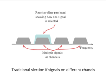
OFDM is a form of multicarrier modulation. An OFDM signal consists of a number of closely spaced modulated carriers. When modulation of any form - voice, data, etc. is applied to a carrier, then sidebands spread out either side. It is necessary for a receiver to be able to receive the whole signal to be able to successfully demodulate the data. As a result when signals are transmitted close to one another they must be spaced so that the receiver can separate them using a filter and there must be a guard band between them. This is not the case with OFDM. Although the sidebands from each carrier overlap, they can still be received without the interference that might be expected because they are orthogonal to each another. This is achieved by having the carrier spacing equal to the reciprocal of the symbol period.
Traditional-slection if signals on different chanels
To see how OFDM works, it is necessary to look at the receiver. This acts as a bank of demodulators, translating each carrier down to DC. The resulting signal is integrated over the symbol period to regenerate the data from that carrier. The same demodulator also demodulates the other carriers. As the carrier spacing equal to the reciprocal of the symbol period means that they will have a whole number of cycles in the symbol period and their contribution will sum to zero - in other words there is no interference contribution.
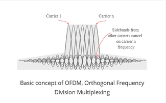
Basic concept of OFDM, Orthogonal Frequency Division Multiplexing
One requirement of the OFDM transmitting and receiving systems is that they must be linear. Any non-linearity will cause interference between the carriers as a result of inter-modulation distortion. This will introduce unwanted signals that would cause interference and impair the orthogonality of the transmission.
In terms of the equipment to be used the high peak to average ratio of multi-carrier systems such as OFDM requires the RF final amplifier on the output of the transmitter to be able to handle the peaks whilst the average power is much lower and this leads to inefficiency. In some systems the peaks are limited. Although this introduces distortion that results in a higher level of data errors, the system can rely on the error correction to remove them.
Data on OFDM
The traditional format for sending data over a radio channel is to send it serially, one bit after another. This relies on a single channel and any interference on that single frequency can disrupt the whole transmission.
OFDM adopts a different approach. The data is transmitted in parallel across the various carriers within the overall OFDM signal. Being split into a number of parallel "substreams" the overall data rate is that of the original stream, but that of each of the substreams is much lower, and the symbols are spaced further apart in time.
This reduces interference among symbols and makes it easier to receive each symbol accurately while maintaining the same throughput.
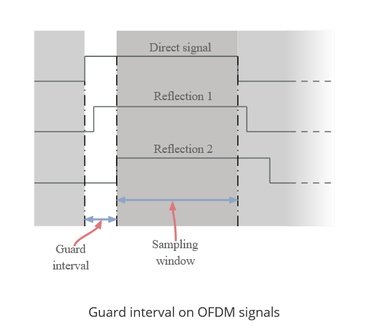
The lower data rate in each stream means that the interference from reflections is much less critical. This is achieved by adding a guard band time or guard interval into the system. This ensures that the data is only sampled when the signal is stable and no new delayed signals arrive that would alter the timing and phase of the signal. This can be achieved far more effectively within a low data rate substream.
Guard interval on OFDM signals
The distribution of the data across a large number of carriers in the OFDM signal has some further advantages. Nulls caused by multi-path effects or interference on a given frequency only affect a small number of the carriers, the remaining ones being received correctly. By using error-coding techniques, which does mean adding further data to the transmitted signal, it enables many or all of the corrupted data to be reconstructed within the receiver. This can be done because the error correction code is transmitted in a different part of the signal.
Key features of OFDM
The OFDM scheme differs from traditional FDM in the following interrelated ways:
- Multiple carriers (called subcarriers) carry the information stream
- The subcarriers are orthogonal to each other.
- A guard interval is added to each symbol to minimize the channel delay spread and intersymbol interference.
OFDM advantages & disadvantages
OFDM advantages
OFDM has been used in many high data rate wireless systems because of the many advantages it provides.
- Immunity to selective fading: One of the main advantages of OFDM is that is more resistant to frequency selective fading than single carrier systems because it divides the overall channel into multiple narrowband signals that are affected individually as flat fading sub-channels.
- Resilience to interference: Interference appearing on a channel may be bandwidth limited and in this way will not affect all the sub-channels. This means that not all the data is lost.
- Spectrum efficiency: Using close-spaced overlapping sub-carriers, a significant OFDM advantage is that it makes efficient use of the available spectrum.
- Resilient to ISI: Another advantage of OFDM is that it is very resilient to inter-symbol and inter-frame interference. This results from the low data rate on each of the sub-channels.
- Resilient to narrow-band effects: Using adequate channel coding and interleaving it is possible to recover symbols lost due to the frequency selectivity of the channel and narrow band interference. Not all the data is lost.
- Simpler channel equalisation: One of the issues with CDMA systems was the complexity of the channel equalisation which had to be applied across the whole channel. An advantage of OFDM is that using multiple sub-channels, the channel equalization becomes much simpler.
OFDM disadvantages
Whilst OFDM has been widely used, there are still a few disadvantages to its use which need to be addressed when considering its use.
- High peak to average power ratio: An OFDM signal has a noise like amplitude variation and has a relatively high large dynamic range, or peak to average power ratio. This impacts the RF amplifier efficiency as the amplifiers need to be linear and accommodate the large amplitude variations and these factors mean the amplifier cannot operate with a high efficiency level.
- Sensitive to carrier offset and drift: Another disadvantage of OFDM is that is sensitive to carrier frequency offset and drift. Single carrier systems are less sensitive.
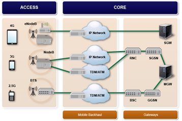
OFDM, orthogonal frequency division multiplexing has gained a significant presence in the wireless market place. The combination of high data capacity, high spectral efficiency, and its resilience to interference as a result of multi-path effects means that it is ideal for the high data applications that have become a major factor in today's communications scene.
Use of cyclic prefix is a key element of enabling the OFDM signal to operate reliably.
The cyclic prefix acts as a buffer region or guard interval to protect the OFDM signals from intersymbol interference. This can be an issue in some circumstances even with the much lower data rates that are transmitted in the multicarrier OFDM signal.
What is a cyclic prefix
The basic concept behind the OFDM cyclic prefix is quite straightforward. The cyclic prefix performs two main functions.
- The cyclic prefix provides a guard interval to eliminate intersymbol interference from the previous symbol.
- It repeats the end of the symbol so the linear convolution of a frequency-selective multipath channel can be modeled as circular convolution, which in turn may transform to the frequency domain via a discrete Fourier transform. This approach accommodates simple frequency domain processing, such as channel estimation and equalization.
The cyclic prefix is created so that each OFDM symbol is preceded by a copy of the end part of that same symbol.
Different OFDM cyclic prefix lengths are available in various systems. For example within LTE a normal length and an extended length are available and after Release 8 a third extended length is also included, although not normally used.
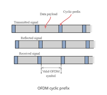
Cyclic prefix advantages and disadvantages
There are several advantages and disadvantages attached to the use for the cyclic prefix within OFDM.
Advantages
- Provides robustness: The addition of the cyclic prefix adds robustness to the OFDM signal. The data that is retransmitted can be used if required.
- Reduces inter-symbol interference: The guard interval introduced by the cyclic prefix enables the effects of inter-symbol interference to be reduced.
Disadvantages
- Reduces data capacity: As the cyclic prefix re-transmits data that is already being transmitted, it takes up system capacity and reduces the overall data rate.
The use of a cyclic prefix is standard within OFDM and it enables the performance to be maintaiend even under conditions when levels of reflections and multipath propagation are high.
One of the key requirements for optimum demodulation of OFDM signals is that there is accurate frequency and timing synchronisation.
Fortunately good OFDM timing and frequency synchronisation is relatively easy to obtain as accurate signals are easy to derive.
Poor timing and frequency synchronisation result in significant levels of degradation to the signal, and as a result this aspect of the signal chain is key to optimum performance.


OFDM synchronization basics
OFDM offers many advantages in terms of resilience to fading, reflections and the like. OFDM also offers a high level of spectrum efficiency. However to reap the rewards, it is necessary that the OFDM system operates correctly, and to achieve this, it is necessary for the OFDM synchronization to be effective.
There are a number of areas in which the OFDM synchronisation is critical to the operation of the system:
- OFDM synchronization in terms of frequency offset: It is necessary that the frequencies are accurately tracked to ensure that orthogonality is maintained.
- OFDM synchronisation in terms of clock accuracy: It is necessary that the sampling occurs at the correct time interval to ensure that the samples are synchronized and data errors are minimised.
In order to ensure that the OFDM system works to its optimum, it is necessary to ensure that there are schemes in place to ensure the OFDM synchronization is within the required limits.
Frequency offset OFDM synchronization
It is particularly important that the demodulator in an OFDM receiver is able to synchronize accurately with the carriers within the OFDM signal. Offsets may arise for a number of reasons including any frequency errors between the transmitter and the receiver and also as a result of Doppler shifts if there is movement between the transmitter and receiver.
If the frequency synchronisation is impaired, then the orthogonality of the carriers is reduced within the demodulation process and error rates increase. Accordingly it is essential to maintain orthogonality to reduce errors and maintain the performance of the link.
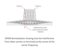
First look at the way that sampling should occur. With the demodulator in synchronisation, all the contributions from the other carriers sum to zero as shown. On this way all the carriers are orthogonal and the error rate is at its minimum.
If a situation is encountered where the OFDM synchronisation for the frequency aspects are poor, then the demodulator will centre its samples away from the peak of the signal, and also at a point where the contributions from the other signals do not sum to zero. This will lead to a degradation of the signal which could in turn lead to an increase in the number of bit errors.
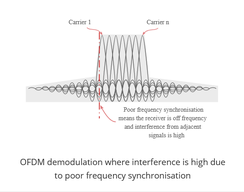
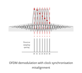
Clock offset OFDM synchronization
It is also necessary to maintain OFDM synchronization in terms of the clock. Gain if the clock synchronisation is not accurate, sampling will be offset and again orthogonality will be reduced, and data errors will increase.
When looking at OFDM synchronization with regard to the clock offset, the carrier spacing used within the receiver for sampling the received signal will be based upon the internal clock rate. If this differs from that used within the transmitter, it will be found that even if the first carrier within the multiplex is correct, then there will be a growing discrepancy with each carrier away from the first one. Even small levels of discrepancy will cause the error rate to increase.
When using OFDM it is necessary to ensure that the synchronisation for both timing and frequency is accurate. By ensuring accurate synchronisation, it is possible to perform the optimum demodulation of the signal. Any misalignment causes the receiver to start to pick up the unwanted interference signals. Fortunately it is relatively easy to obtain accurate synchronisation signals as these are available from the network, and short term synchronisation can be generated internally.
Radio technology and radio frequency design or RF design are key to the operation of many items like radios, mobile phones, Wi-Fi routers and many other radio based devices.
Understanding the building blocks used and the techniques adopted enables RF design, maintenance and usage to be undertaken effectively.
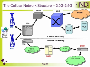
Radio signals and modulation
There are many different forms of radio signal that can be used. From simple forms of modulation like amplitude, frequency and phase modulation, through to complex waveforms using techniques like direct sequence spread spectrum and orthogonal frequency division multiplexing, there are many different techniques and technologies used in radio frequency engineering.
The descriptions of the different types of modulation and waveform are in many cases accompanied by the electronic circuits used for their modulation and demodulation. These are useful for the RF design of circuits that need to process these forms of modulation.

RF Building blocks
There are many different electronic circuit building blocks used in radio frequency design. There are electronic circuit blocks like mixers, attenuators, and filters which are widely used for RF design. You may find more information about them from the links provided.
- Modulation types & techniques
- Amplitude modulation, AM
- Frequency modulation, FM
- Phase modulation, PM
- Quadrature amplitude modulation, QAM
- Multicarrier modulation
- Direct sequence spread spectrum
- Phase locked loop, PLL
- Frequency synthesizers
- RF mixers
- RF attenuators
- RF filters
- RF circulator
- Splitters combiners, couplers & hybrids
- Passive intermodulation primer
- Doherty amplifier
- Envelope tracking
Radio receivers
An important area of RF design is associated with radio receiver design. There are many different forms of radio receiver, each type with its own characteristics. The different specifications and parameters used within he RF design and specification of these different techniques are also described.
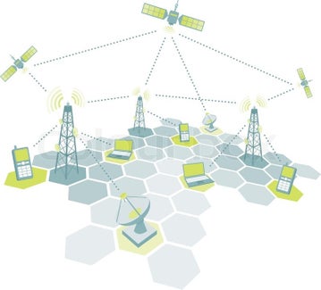
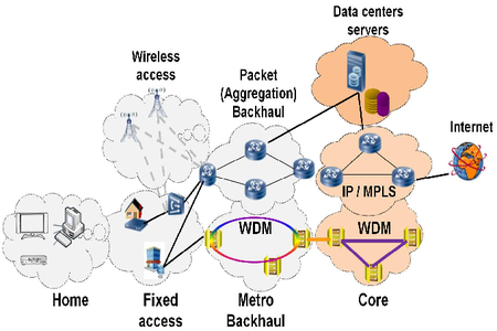
Basics of radio
This section will look at some of the basic elements of radio and what it is:
With the increasing amount of all forms of wireless communication for everything from mobile / cellular communications to applications like Wi-Fi and the many other wireless standards, radio frequency or RF design and RF technology in general are of great importance. Even if you re not directly involved in RF design or setting up applications for wireless and radio communications, an understanding of RF technology and RF techniques can be very useful.